Electricity and Magnetism: Charge, Circuits, and Fields
Circuit Boss: Power Up Your Physics ⚡
Introduction
1. Introduction
Alright, let's talk electricity and magnetism. Every time you charge your phone, flick a light switch, or feel a static shock off a doorknob, this chapter is running in the background. It's the biggest topic in Core Physics and easily the most useful one for real life, because basically everything that plugs in or runs on a battery obeys these rules. We're going to go from invisible charges and magnetic fields all the way to circuits, household wiring, motors, and the transformers humming on the power lines outside. By the end you'll be reading circuit diagrams like song lyrics and explaining why a bird on a power line doesn't get fried. Let's power up! ⚡
2. Magnets, Poles and Field Lines
Every magnet has a north pole and a south pole, and the golden rule is like poles repel, unlike poles attract. The space around a magnet where it can push or pull is the magnetic field, and we draw it with field lines that always point from north to south outside the magnet. The direction of the field at a point is the direction of the force on a north pole placed there, and the lines never cross. Magnetic materials are iron, steel, cobalt and nickel; everything else (copper, plastic, wood) is non-magnetic. You can turn a piece of unmagnetised iron into a temporary magnet just by bringing a magnet near it: that's induced magnetism, and it's why a magnet picks up a chain of paper clips. 🧲
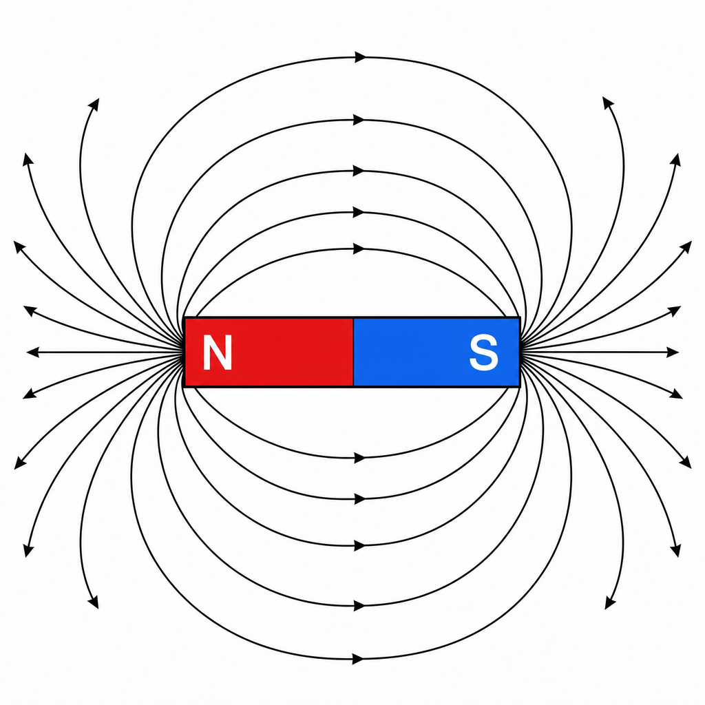
Key idea🔑 Key idea: Like poles repel, unlike attract. Field lines run N → S outside the magnet: the field direction is the force on a N pole.
Worked example
Worked Example: Spotting the Real Magnet
Worked Example: Which Bar Is Magnetised? 🔍
You have two identical steel bars. One is a magnet, one is just plain steel. Without any other equipment, how can you tell which is which?
- 1Bringing the ends together tells you nothing. Only one bar is a magnet, so the bars can never repel: the magnet attracts plain steel at either end.
- 2Use the fact that a magnet pulls strongly at its ends (poles) but hardly at all at its middle. Touch the end of bar A to the middle of bar B, making a T. If A is the magnet, its pole pulls B's middle strongly. If B is the magnet, A is touching the magnet's middle, where there is almost no pull. So the bar whose end strongly attracts the middle of the other is the magnet. (Or hang each bar on a thread: only the magnet settles pointing north-south.)
---
3. Static Charge: Where Electricity Begins
There are two kinds of electric charge, positive and negative, and just like magnets, like charges repel and unlike charges attract. You create static charge by rubbing (friction): drag a plastic rod through a cloth and electrons (tiny negative charges) get scraped off one and onto the other. The one that gains electrons becomes negative; the one that loses them becomes positive. Only electrons move, never the positive charges. Materials split into conductors (metals, which let charge flow freely because they have loose electrons) and insulators (plastic, rubber, glass, which trap charge in place). That trapped charge is exactly why you build up a zap walking across a carpet and discharge it into the next metal handle you touch. ⚡
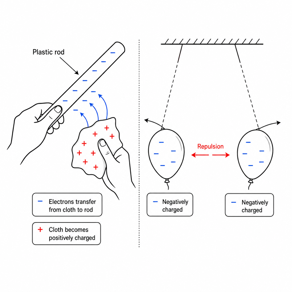
Key idea🔑 Key idea: Charging by friction moves electrons only. Like charges repel, unlike attract. Conductors let charge flow; insulators trap it.
Worked example
Worked Example: The Repelling Balloons
Worked Example: Why Balloons Push Apart 🎈
You rub two balloons on your hair and hang them side by side on threads. They swing apart. Explain why.
- 1Rubbing transfers electrons from your hair onto both balloons, so each balloon gains the same (negative) charge. Like charges repel, so the two negatively charged balloons push each other away and the threads hang at an angle.
---
4. Electric Current: Charge on the Move
An electric current is a flow of charge: the bigger the current, the more charge flows past a point each second. It is measured in amperes (A) with an ammeter connected in series (in the line of the circuit). Ammeters can be analogue (a pointer on a scale) or digital; choose the smallest range that is bigger than the current you expect, so the meter is not overloaded but still reads precisely. In a metal wire the current is carried by free electrons drifting along the wire, while the metal ions stay in place. Current comes in two flavours: direct current (d.c.) from cells and batteries always flows one way, while alternating current (a.c.) from the mains keeps reversing direction. 🔋
Key idea🔑 Key idea: Current is a flow of charge, in amps, measured with an ammeter in series. In metals, free electrons move. d.c. is one-way, a.c. keeps reversing.
Worked example
Worked Example: Choosing an Ammeter Range
Worked Example: Which Range Do You Pick? 🔢
A torch bulb is expected to carry about A. A digital ammeter has ranges of mA, A and A. Which range should you choose, and what is moving in the copper wires?
- 1mA A is smaller than A, so it would overload the meter. A would work but give a less precise reading. Choose A, the smallest range bigger than the expected current.
- 2In the copper wires, free electrons drift along the wire; that drift is the current.
---
5. E.m.f. and Potential Difference: The Push
Charge doesn't move on its own: something has to push it, and that push is voltage, measured in volts (V) with a voltmeter connected in parallel (across the component). There are two voltage words to keep straight. Electromotive force (e.m.f.) is the energy a battery or generator gives to each unit of charge it pushes out: it's the "full strength" of the source. Potential difference (p.d.) is the energy delivered to each unit of charge as it passes through a component, like a bulb or resistor. Same unit (volts), different jobs: e.m.f. is energy in, p.d. is energy spent. Think of the battery as a water pump giving energy to the water, and each component as a waterwheel taking energy back out. 💡
Key idea🔑 Key idea: Voltage is the push, measured in volts with a voltmeter in parallel. E.m.f. = energy given per unit charge by the source; p.d. = energy delivered per unit charge to a component.
Worked example
Worked Example: Voltmeter in the Right Place
Worked Example: Across, Not Along 📏
A student wants to measure the p.d. across a lamp. Where should the voltmeter go, and how is that different from the ammeter?
- 1A voltmeter measures the difference between two points, so it goes in parallel, connected across the two ends of the lamp. The ammeter measures flow through the lamp, so it goes in series, in the line of the circuit. Voltmeter across, ammeter along.
---
6. Resistance and Ohm's Law
Resistance is how much a component opposes the flow of current, measured in ohms (Ω). The defining relationship links voltage, current and resistance:
So for the same push, a bigger resistance means a smaller current. You measure resistance by putting an ammeter (in series) and a voltmeter (in parallel) around the component, then dividing by . Resistance also depends on the wire itself: a longer wire has more resistance (more obstacles for the charge to pass), and a thicker (larger cross-section) wire has less resistance (more lanes for the traffic). So long, thin wires have a high resistance (heating elements) and short, thick wires have a low resistance (connecting leads and mains cables). 🚦
So for the same push, a bigger resistance means a smaller current. You measure resistance by putting an ammeter (in series) and a voltmeter (in parallel) around the component, then dividing by . Resistance also depends on the wire itself: a longer wire has more resistance (more obstacles for the charge to pass), and a thicker (larger cross-section) wire has less resistance (more lanes for the traffic). So long, thin wires have a high resistance (heating elements) and short, thick wires have a low resistance (connecting leads and mains cables). 🚦
Key idea🔑 Key formula: (so ), in ohms. Longer wire → more resistance; thicker wire → less resistance.
Worked example
Worked Example: Sizing a Resistor
Worked Example: Find the Resistance 🧮
A component has a current of A flowing through it when the p.d. across it is V. Find its resistance. Then work out the current if the voltage is raised to V (assume the resistance stays the same).
- 1Write the equation and rearrange for resistance: .
- 2Now use rearranged for current at the new voltage: A.
- 3Doubling the voltage from V to V doubled the current from A to A, exactly what predicts when is fixed.
---
7. Electrical Energy and Power
Power is the rate at which a device transfers electrical energy, measured in watts (W). In a circuit it's the voltage times the current:
and over a time the energy transferred is (in joules). A higher-power device (a kettle, a heater) pulls a bigger current at the same voltage and chews through energy faster. For your electricity bill, joules are far too small, so energy companies bill in kilowatt-hours (kWh): one kWh is the energy a kW device uses in one hour. The cost is just . That's why running a kW heater all evening shows up on the bill while charging a phone barely registers. 💸
and over a time the energy transferred is (in joules). A higher-power device (a kettle, a heater) pulls a bigger current at the same voltage and chews through energy faster. For your electricity bill, joules are far too small, so energy companies bill in kilowatt-hours (kWh): one kWh is the energy a kW device uses in one hour. The cost is just . That's why running a kW heater all evening shows up on the bill while charging a phone barely registers. 💸
Key idea🔑 Key formula: and . Energy bills use kilowatt-hours: .
Worked example
Worked Example: Rating the Kettle
Worked Example: How Much Current, How Much Cost? 🫖
A kettle is rated W and runs from the V mains. (a) What current does it draw? (b) If electricity costs cents per kWh, what does it cost to run the kettle for minutes ( h)?
- 1Rearrange for current: A. That's why kettles need a A fuse, not a A one.
- 2Energy used kWh.
- 3Cost cents. Under cents per cuppa, mostly because the kettle is high-power but only runs for minutes.
---
8. Circuit Diagrams and Symbols
A circuit diagram is a tidy map of a real circuit drawn with standard symbols, so anyone in the world can read it. You need to recognise and draw the symbols for a cell and battery, a switch, a lamp, a resistor and variable resistor, an ammeter (A in a circle) and voltmeter (V in a circle), plus a fuse, a thermistor and an LDR (light-dependent resistor), and the power supply, generator, motor, bell, heater, relay, magnetising coil and transformer. Two are sensors: a thermistor's resistance drops as it heats up; an LDR's resistance drops in bright light. The symbol card in the picture also shows a diode and an LED; you will not be asked to use those two on a Core paper. Drawing components in a neat rectangle with straight wires and right-angle corners is the exam-friendly style. 🗺️
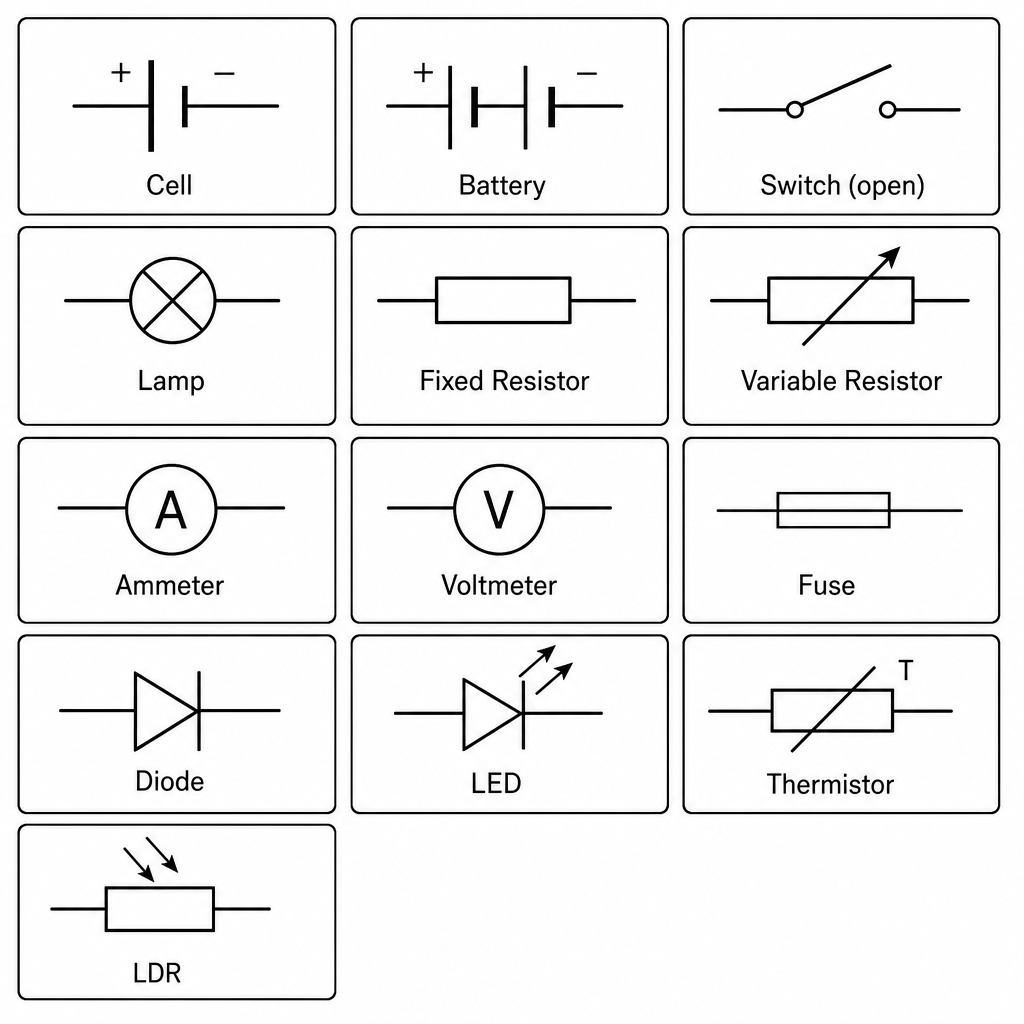
Key idea🔑 Key idea: Learn the standard symbols. Sensors: thermistor = less resistance when hot; LDR = less resistance in light.
Worked example
Worked Example: Reading the Diagram
Worked Example: What Does This Circuit Do? 👀
A circuit shows a cell, a switch, and a lamp all connected in a single loop. A student adds an ammeter and a voltmeter to measure the lamp. Where does each meter go on the diagram?
- 1The ammeter symbol (A in a circle) goes in the loop in series with the lamp, since current is the same all the way round a single loop. The voltmeter symbol (V in a circle) goes across the lamp as a branch, in parallel, to read the p.d. delivered to it.
---
9. Series and Parallel Circuits
Components can be wired two ways. In a series circuit everything sits in a single loop: the current is the same at every point, the combined resistance is (resistances add), and cells facing the same way add their e.m.f.s ( V + V V). If one part of a series loop breaks, everything stops. In a parallel circuit components sit on separate branches: the current from the source is bigger than the current in any one branch, and two resistors in parallel have a combined resistance less than either one (an extra path makes it easier for charge to flow). House lights are wired in parallel: each lamp gets the full mains voltage, each can be switched on and off on its own, and if one fails the others stay on. 🏠
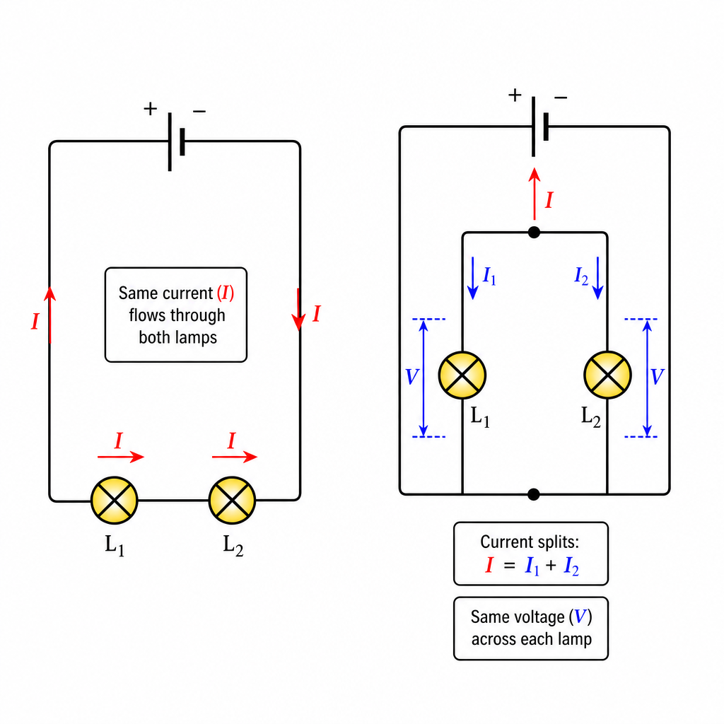
Key idea🔑 Key idea: Series = one loop, same current, resistances add (). Parallel = branches, source current bigger than each branch current, combined resistance less than either resistor.
Worked example
Worked Example: Series and Parallel Resistors
Worked Example: Add Them or Not? 🧮
A V battery is connected to two resistors, and . (a) In series, find the combined resistance and the current in each resistor. (b) In parallel, is the combined resistance more or less than ? Use this to show the battery current is more than A.
- 1In series, resistances add: .
- 2The current from the battery uses the total resistance: A, and this same current flows through both resistors because it's a single loop.
- 3In parallel, two resistors have a combined resistance less than either, so less than . Through exactly , V would drive A. The real resistance is smaller, so the battery current is more than A, far more than the series case.
---
10. Potential Dividers
If the current through a conductor stays the same, means the p.d. across it increases as its resistance increases. Put two resistors in series across a supply and they share the supply p.d. between them: that's a potential divider. The same current flows through both, so the larger resistance has the larger p.d., and two equal resistors take half each. The method: find the current from the combined resistance, then use for each resistor. Put a thermistor or an LDR in series with a fixed resistor and the p.d.s change with temperature or light, which is the heart of simple sensor circuits (a temperature alarm, an automatic night light). ⚖️
Key idea🔑 Key idea: Same current, bigger resistance → bigger p.d. Find the current first, then for each resistor.
Worked example
Worked Example: Sharing the Volts
Worked Example: Who Gets More Voltage? ⚖️
A V supply is connected across two resistors in series, and . Find the current and the p.d. across each resistor. Which has the larger p.d., and why?
- 1Combined resistance , so the current is A through both.
- 2V and V. The resistor has the larger p.d.: same current, bigger resistance, bigger p.d. Check: V.
---
11. Electrical Safety at Home
Mains electricity is genuinely dangerous, so a UK-style plug has three wires with fixed colours: live (brown, carries the dangerous voltage), neutral (blue, completes the circuit), and earth (green/yellow, a safety wire to the metal case). The fuse is a thin wire that melts and breaks the circuit if too big a current flows (a short circuit or a fault), cutting the power before wires overheat and start a fire. The earth wire plus fuse protects metal-cased appliances: if the live wire touches the case, a huge current flows to earth, blows the fuse, and makes the case safe. Appliances with plastic cases use double insulation instead (no earth needed), because the case can never become live. Trip switches (circuit breakers) do the fuse's job but reset with a flick instead of needing replacement. ⚠️
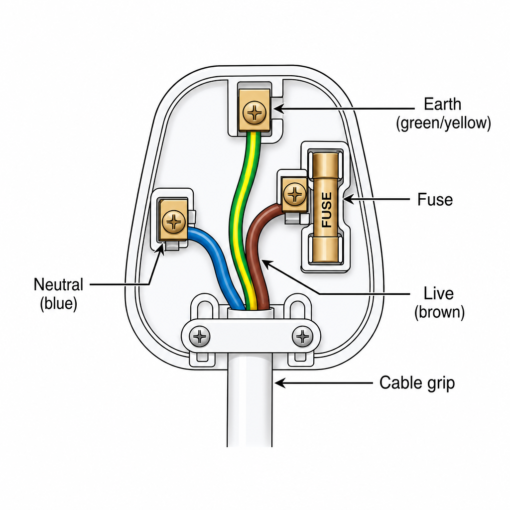
Key idea🔑 Key idea: Live (brown), neutral (blue), earth (green/yellow). The fuse melts to break a dangerous current; earth + fuse make metal cases safe; plastic cases use double insulation.
Worked example
Worked Example: Picking the Right Fuse
Worked Example: 3 A or 13 A? 🔥
A lamp is rated V, W. Fuses come in A and A. Which one should you fit?
- 1Find the normal current: A. Pick the smallest fuse rated just above the normal current, so the A fuse is correct: it carries A fine but blows quickly on a fault. A A fuse would let a dangerous fault current flow before melting.
---
12. Electromagnetic Induction
Here's the magic that powers the world: move a magnet near a coil of wire (or move a wire through a magnetic field) and you induce a voltage (e.m.f.) across the wire. No battery, no contact: just relative movement between a conductor and a magnetic field. If the wire is part of a complete circuit, that induced voltage drives an induced current. The induced voltage is bigger if you move the magnet faster, use a stronger magnet, or use more turns on the coil. Stop moving and the voltage vanishes: it's the change that matters. The generators in power stations use this effect to make electricity. 🌀
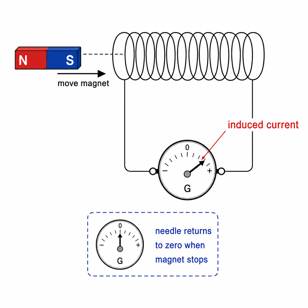
Key idea🔑 Key idea: Moving a magnet and coil relative to each other induces a voltage. Faster movement, stronger magnet, or more turns = bigger induced e.m.f. Stop moving → no voltage.
Worked example
Worked Example: The Flicking Needle
Worked Example: Why the Meter Twitches 🪄
A magnet is pushed into a coil connected to a meter; the needle flicks, then returns to zero even though the magnet is still inside. Explain why.
- 1A voltage is induced only while the magnetic field through the coil is changing, which happens while the magnet is moving in. Once the magnet stops, the field is steady, nothing changes, so no voltage is induced and the needle drops back to zero. Pull the magnet back out and the needle flicks the other way.
---
13. The Magnetic Effect of a Current
It works in reverse too: an electric current creates a magnetic field around itself. A straight wire makes circular field lines around it; coil the wire into a solenoid and its field has the same pattern as a bar magnet's, with a north end and a south end. You can show either pattern with iron filings on a card (the shape) and plotting compasses (the direction); reverse the current and every compass turns round. Put a soft-iron core in the solenoid and you've built an electromagnet: the iron makes the field much stronger, and the magnetism switches off when the current stops. This switchable magnetism runs relays (a small current switches a big one), electric bells, loudspeakers (current variations push a cone to make sound) and the giant electromagnets that lift cars in scrapyards. 🧲
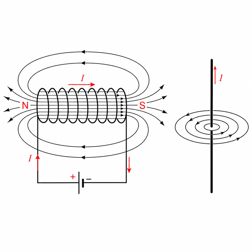
Key idea🔑 Key idea: A current makes a magnetic field. A solenoid acts like a bar magnet; add an iron core for a switchable electromagnet. Used in relays, bells, and loudspeakers.
Worked example
Worked Example: Why a Relay Uses Two Circuits
Worked Example: Small Switch, Big Motor 📎
A car's starter motor needs a very large current, but the ignition switch on the dashboard only carries a small one. Explain how a relay lets the small switch start the motor.
- 1Turning the key sends a small current through the relay's coil, which is wound on a soft-iron core, so it becomes an electromagnet.
- 2The electromagnet pulls an iron armature, which pushes two contacts together in a separate circuit containing the battery and the starter motor. The big current flows in that second circuit only, so the dashboard switch stays small and safe.
---
14. Force on a Current in a Magnetic Field
A wire carrying a current across a magnetic field feels a force. This is the motor effect. To show it, rest a light copper rod across two copper rails that run between the poles of a U-shaped magnet, and connect the rails to a low-voltage d.c. supply: switch on and the rod rolls along the rails. Crucially, if you reverse the current or reverse the field, the force reverses direction; reverse both and it stays the same. Increase the current or use a stronger magnet and the push gets bigger. This single effect is what makes every electric motor and loudspeaker move. 💪
Key idea🔑 Key idea: A current in a magnetic field feels a force (the motor effect). Reverse the current or the field → force reverses; reverse both → no change.
Worked example
Worked Example: Reversing the Push
Worked Example: Which Way Does the Wire Jump? ↕️
A wire between two magnet poles jumps upward when the current flows. What happens if you reverse the battery, and what happens if you also swap the magnet poles?
- 1Reversing the current alone flips the force, so the wire jumps downward. If you then also swap the magnet poles, you reverse the field too, and two reversals cancel: the wire jumps upward again, just like at the start.
---
15. The d.c. Motor
A d.c. motor turns electrical energy into kinetic energy using the motor effect. A coil that can spin on an axle sits between magnet poles. The current goes one way along one side of the coil and back the other way along the other side, and reversing the current reverses the force, so one side is pushed up and the other down: the coil has a turning effect. The turning effect is bigger with more turns on the coil, a bigger current, or a stronger magnet. The picture also labels the parts that keep a real motor turning past the half-turn; how they work is Extended, so at Core explain why the coil turns and what makes it turn harder. Every fan, drill, electric car and washing machine runs on this idea. 🔄
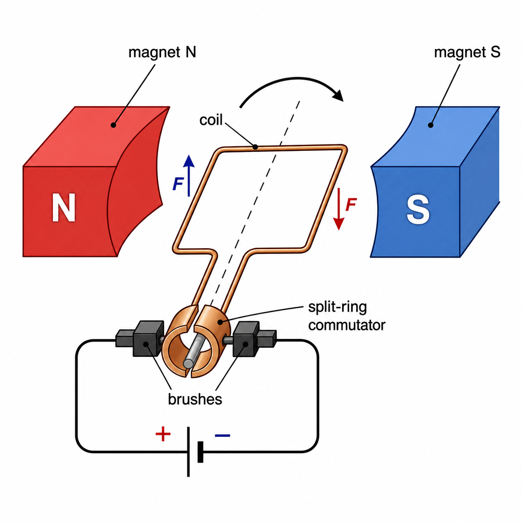
Key idea🔑 Key idea: Opposite forces on the two sides of a current-carrying coil give it a turning effect. More turns, more current, or a stronger magnet → bigger turning effect.
Worked example
Worked Example: Why the Coil Turns
Worked Example: Up One Side, Down the Other 🔁
A coil carrying a current sits on an axle between the poles of a magnet. Explain why it turns, and state three ways to make the turning effect bigger.
- 1The current flows in opposite directions along the two long sides of the coil. A current in a magnetic field feels a force, and reversing the current reverses the force, so one side is pushed up and the other down. Those two forces on either side of the axle turn the coil, transferring electrical energy to kinetic energy.
- 2Bigger turning effect: more turns on the coil, a bigger current, or a stronger magnet.
---
16. The Transformer
A transformer changes the size of an alternating (a.c.) voltage. It has a soft-iron core with two coils: a primary coil connected to the a.c. input and a secondary coil connected to the output. The coils are not connected to each other; only the iron core links them. The voltage changes in the same ratio as the turns:
More turns on the secondary (a step-up transformer) gives a higher output voltage; fewer turns (step-down) gives a lower one. Transformers are why power is sent across the country at very high voltage: a step-up transformer at the power station raises the voltage, and for the same power the current is then much smaller, so far less energy is wasted heating the cables and thinner, cheaper cables can be used. Step-down transformers near homes lower it again to about V. ⚡
More turns on the secondary (a step-up transformer) gives a higher output voltage; fewer turns (step-down) gives a lower one. Transformers are why power is sent across the country at very high voltage: a step-up transformer at the power station raises the voltage, and for the same power the current is then much smaller, so far less energy is wasted heating the cables and thinner, cheaper cables can be used. Step-down transformers near homes lower it again to about V. ⚡
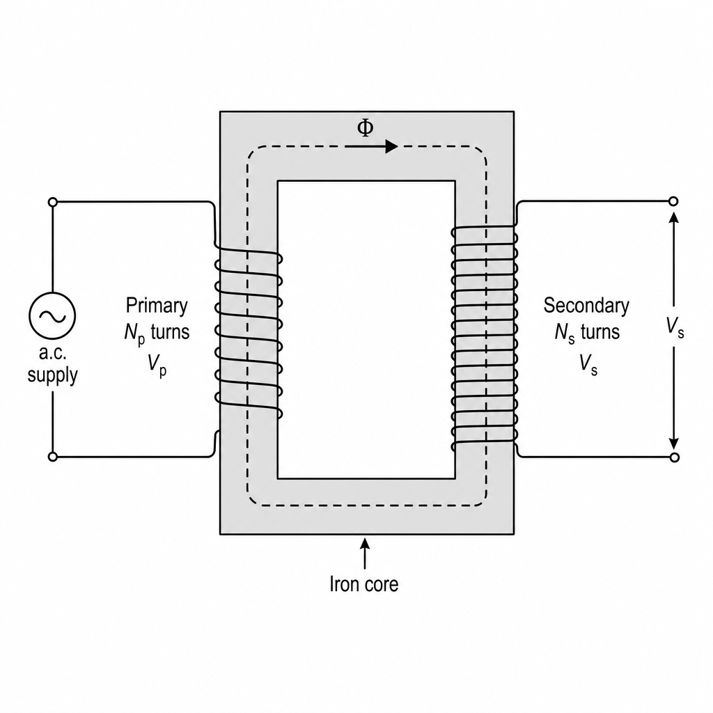
Key idea🔑 Key formula: . More secondary turns = step-up; fewer = step-down. High-voltage transmission → smaller current → less energy wasted in the cables.
Worked example
Worked Example: Step-Down for the House
Worked Example: From Pylon to Plug 🏠
A step-down transformer must change V from a local substation to V for homes. The primary has turns. How many turns are on the secondary?
- 1Write the transformer equation and rearrange for the secondary turns: , so .
- 2Substitute the values: turns.
- 3The secondary has just turns versus the primary's , a ratio that matches the voltage ratio. Far fewer turns on the output side: that's what makes it step down.
---
Practice this in the app
Unlock the full chapter: practice questions, flashcards, mock papers and notes, free.
Continue revising