Electricity and Magnetism: Charge, Circuits, Fields and Machines
Circuit Boss: Wire It Up ⚡
Introduction
1. Introduction
Alright, the biggest chapter in the syllabus, and the one hiding inside everything you own. Why does your phone charger turn 230 V into 5 V, why do fairy lights all die when one bulb blows, why does a fridge magnet stick but a power line kill, why does waving a magnet near a coil make free electricity? Same toolkit every time: charge, the push that moves it, the resistance that slows it, and the deep link between electricity and magnetism that runs every motor and generator on Earth.
This is your fast refresh, not the full textbook. One key formula per concept, one quick worked example, and the exact sentence the marker wants. Lock in , and the transformer ratio, learn to tell series from parallel at a glance, and get the right-hand and left-hand rules straight. Let's wire it up! ⚡
This is your fast refresh, not the full textbook. One key formula per concept, one quick worked example, and the exact sentence the marker wants. Lock in , and the transformer ratio, learn to tell series from parallel at a glance, and get the right-hand and left-hand rules straight. Let's wire it up! ⚡
2. Magnets and Magnetic Fields
A magnetic field is the region where a magnet pushes or pulls other magnets and magnetic materials. We draw it with field lines that leave the north pole and enter the south pole, and the rule that earns Extended marks is about spacing: where the lines are close together the field is strong, where they spread apart it is weak. Like poles repel, unlike poles attract, and only iron, steel, cobalt and nickel are magnetic. A plotting compass always points along the line, so it maps the field.
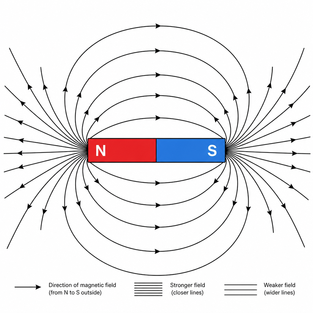
Key idea🔑 Key idea: Field lines go N → S outside the magnet; close lines = strong field, spread lines = weak field. Like poles repel, unlike attract.
Worked example
Worked Example: Which Magnet Is Stronger
Worked Example: Read the Spacing 💪
Two bar magnets are mapped with iron filings. Magnet A's field lines are bunched tightly near its poles; magnet B's are more spread out. Which magnet is stronger, and how do you know?
- 1Field strength is shown by line spacing. Magnet A has lines packed closer together near its poles, so its field is stronger there. Closer lines always mean a stronger field, so magnet A wins.
---
3. Electric Charge and Electric Fields
There are two charges, positive and negative; like charges repel, unlike attract, and charge is measured in coulombs (C). Rub an insulator and you transfer electrons (negative): the object that gains electrons is negative, the one that loses them is positive. You can detect charge with a gold-leaf electroscope: touch a charged rod on its metal cap, the charge spreads over the cap, rod and leaf, the leaf and rod repel, and the leaf rises (more charge, higher leaf). Touch the cap with a finger and the charge flows away to earth, so the leaf falls. An electric field is the region where a charge feels a force, drawn with lines from positive to negative (the direction of the force on a positive charge). The Extended skill is recognising the standard patterns: radial around a point charge or charged conducting sphere, and uniform (parallel, evenly spaced) between two oppositely charged plates.
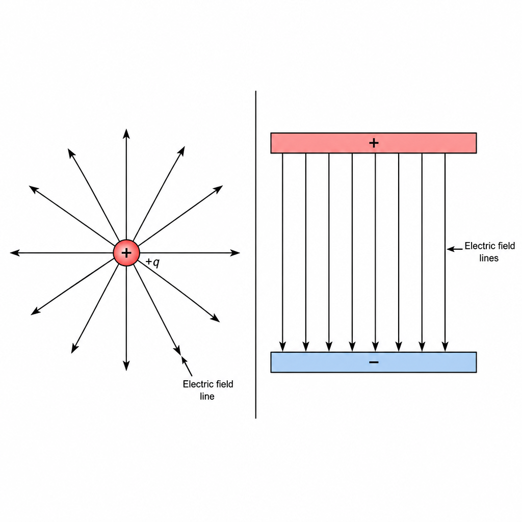
Key idea🔑 Key idea: Field lines run positive → negative. Radial round a point/sphere; uniform (parallel, equal spacing) between plates. Charging moves electrons, never protons. A gold-leaf electroscope's leaf rises when it is charged.
Worked example
Worked Example: Charging a Rod by Friction
Worked Example: Rub, Lose, Charge 🎈
A polythene rod rubbed with a dry cloth becomes negatively charged. Explain what moved and why the cloth ends up positive.
- 1Friction transfers electrons from the cloth to the rod. The rod gains electrons so it is negative; the cloth loses the same electrons so it is left positive. Protons never move: charging is always about where the electrons go.
---
4. Electric Current
Current is the rate of flow of charge: , measured in amperes (1 A = 1 C/s). In a metal the moving charges are free electrons. Two direction conventions clash, so know both: conventional current flows from + to − around the circuit, while the electrons actually drift the opposite way, from − to +. Direct current (d.c.) flows one way only; alternating current (a.c.) reverses direction repeatedly.
Key idea🔑 Key formula: , so . Conventional current: + to −. Electron flow: − to + (opposite).
Worked example
Worked Example: Charge Through a Wire
Worked Example: Amps × Seconds 🔌
A current of A flows through a lamp for s. How much charge passes through it?
- 1Use with A and s:
- 2So 12 coulombs of charge pass through the lamp. Bigger current or longer time both deliver more charge, exactly as predicts.
---
5. E.m.f. and Potential Difference
Voltage is energy per unit charge, measured in volts (1 V = 1 J/C). E.m.f. (electromotive force) is the electrical work done by a source in moving a unit charge around a complete circuit; potential difference (p.d.) is the work done by a unit charge passing through a component. Both are measured with a voltmeter connected in parallel across the component. A bigger voltage means each coulomb carries more energy.
Key idea🔑 Key idea: (1 V = 1 J/C). E.m.f. = work done by the source per unit charge round the circuit; p.d. = work done by a unit charge through a component. Voltmeter goes in parallel.
Worked example
Worked Example: Energy from a Cell
Worked Example: Battery Bookkeeping 🔋
A 12 V cell pushes C of charge around a circuit. How much energy does it transfer to that charge?
- 1Voltage is energy per coulomb, so J. The cell hands 48 J to the charge it pushes.
---
6. Resistance
Resistance opposes current: , measured in ohms (Ω). The defining equation is . The Extended twist is the shape of the I-V graph. A metal resistor at constant temperature is ohmic: current is proportional to voltage, so the graph is a straight line through the origin. A filament lamp heats up as current rises, its resistance climbs, and the graph curves over. A diode only conducts one way, so its graph is flat (no current) in reverse and rises sharply once forward. For a wire, resistance is directly proportional to length and inversely proportional to cross-sectional area: double the length, double the resistance; double the area, half the resistance.
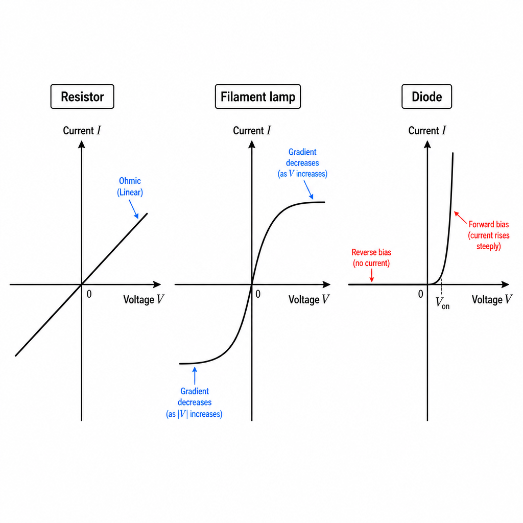
Key idea🔑 Key formula: (so ). Resistor = straight line (ohmic); lamp = curve (R rises as it heats); diode = one-way.
Worked example
Worked Example: Resistance of a Heater
Worked Example: Two Numbers, One Ohm Value 🔢
A heating element carries A when connected across V. Find its resistance.
- 1Rearrange to :
- 2The element has a resistance of 46 Ω. Notice that for a fixed resistance, raising the voltage would raise the current in proportion, the straight-line ohmic behaviour.
---
7. Electrical Energy and Power
Power is energy transferred per second: , measured in watts (W). For a resistor, putting into it gives , the form used for heating in cables. Energy transferred is power × time: . This is exactly what your electricity meter charges for, in kilowatt-hours: kWh is kW for hour, and cost = kWh × price per kWh.
Key idea🔑 Key formulas: and , and energy . Power in watts, energy in joules (or kWh on a bill).
Worked example
Worked Example: Cost of Running a Heater
Worked Example: How Much Did You Burn? 🔥
A W heater runs for minutes (= s). How much electrical energy does it use?
- 1Use with W and s:
- 2That is 3.6 MJ, or kW h on the meter (a 2 kW heater for half an hour). Power tells you the rate; multiply by time for the energy you pay for.
---
8. Circuit Diagrams and Components
Circuits are drawn with standard symbols: cell, battery, power supply, generator, switch, lamp, resistor, variable resistor, heater, ammeter (A, in series), voltmeter (V, in parallel), fuse, thermistor, LDR, motor, magnetising coil, transformer, relay, potential divider, diode and LED. The Extended additions are the diode and LED, which conduct in one direction only. An LED also emits light when current flows forward, and like all diodes it must be the right way round (forward biased) or no current flows at all.
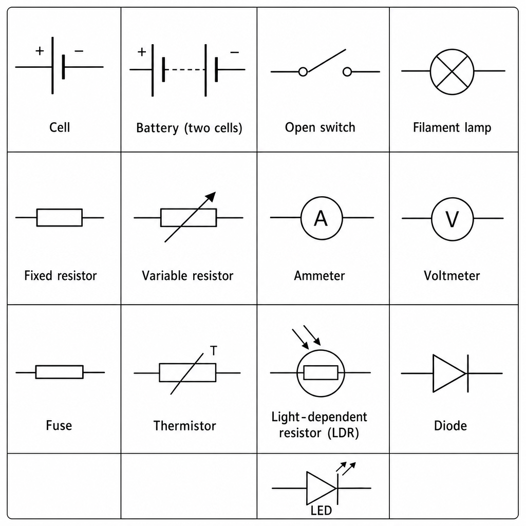
Key idea🔑 Key idea: Ammeter in series, voltmeter in parallel. Diode and LED conduct one way only; an LED also lights when forward biased.
Worked example
Worked Example: Will the LED Light?
Worked Example: Forward Bias or Bust 💡
An LED is connected so that the cell's positive terminal reaches its bar (cathode) side. Will it light?
- 1A diode conducts only when forward biased: positive to the triangle (anode), not the bar. Here the polarity is reversed, so no current flows and the LED stays dark. Flip it round and it lights.
---
9. Series and Parallel Circuits
In series, components share one loop: the current is the same everywhere, resistances add (), and the voltages across components add up to the supply. In parallel, components sit on separate branches: each branch gets the full supply voltage, the branch currents add up to the total, and the combined resistance is less than the smallest branch, from This is why all old fairy lights die together (series) but house sockets keep working independently (parallel).
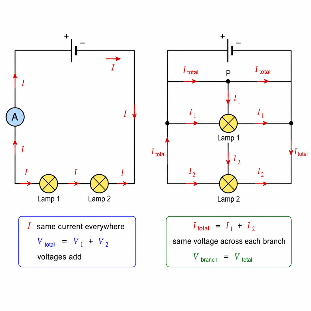
Key idea🔑 Key formulas: Series: same, , voltages add. Parallel: same on each branch, currents add, .
Worked example
Worked Example: Two Resistors in Parallel
Worked Example: The Reciprocal Hack 🧠
A Ω resistor and a Ω resistor are connected in parallel across a V supply. Find the combined resistance and the total current from the supply.
- 1Combine using the reciprocal rule:
- 2The combined resistance ( Ω) is smaller than either branch, as parallel always is. Total current:
That 3.0 A splits between the branches (1.0 A through the 6 Ω, 2.0 A through the 3 Ω) and recombines, the branch currents adding to the total.
---
Answer
10. Potential Dividers
Two resistors in series across a supply split the voltage in proportion to their resistances: the bigger resistor gets the bigger share, with . Swap one resistor for a thermistor or LDR and the output voltage changes with temperature or light, which is how sensor circuits work. A variable potential divider gives a smoothly adjustable output from zero up to the full supply.
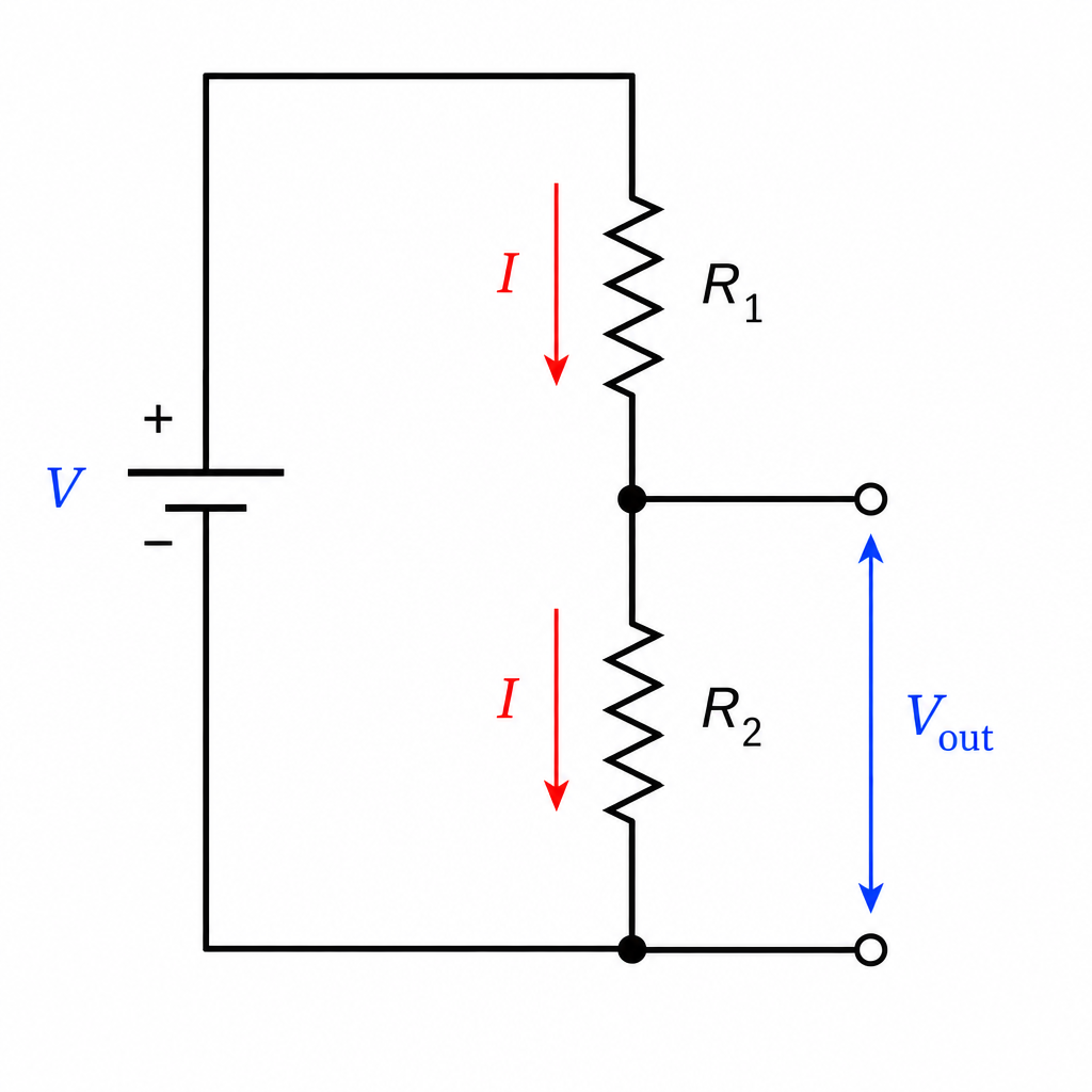
Key idea🔑 Key formula: Series resistors split voltage: . Output across is .
Worked example
Worked Example: Output of a Divider
Worked Example: Take Your Share ⚖️
A V supply is across a Ω and an Ω resistor in series. What voltage appears across the Ω resistor?
- 1The Ω resistor takes its share of the supply:
The bigger resistor (8 Ω) gets the bigger slice (8 V), leaving 4 V across the 4 Ω.
---
Answer
11. Electrical Safety
A UK three-pin plug carries three wires: live (brown, carries the supply), neutral (blue, completes the circuit), and earth (green/yellow, a safety path to ground). The hazards are damaged insulation, overheating cables, damp conditions and overloaded plugs, leads and sockets. The switch goes in the live wire, so that turning it off disconnects the appliance from the high p.d. A fuse is a thin wire in the live side that melts and breaks the circuit if the current grows too large, and it must be rated just above the appliance's normal current; a trip switch (circuit breaker) switches off automatically above its setting and can be reset. The earth wire is not in the live path: it connects a metal case to earth, so if the live wire touches the case, a huge current flows through the live wire, the case and the earth wire, and the fuse in the live wire melts before anyone is shocked. Double-insulated appliances use a plastic case instead and need no earth; their fuse still protects the cable.
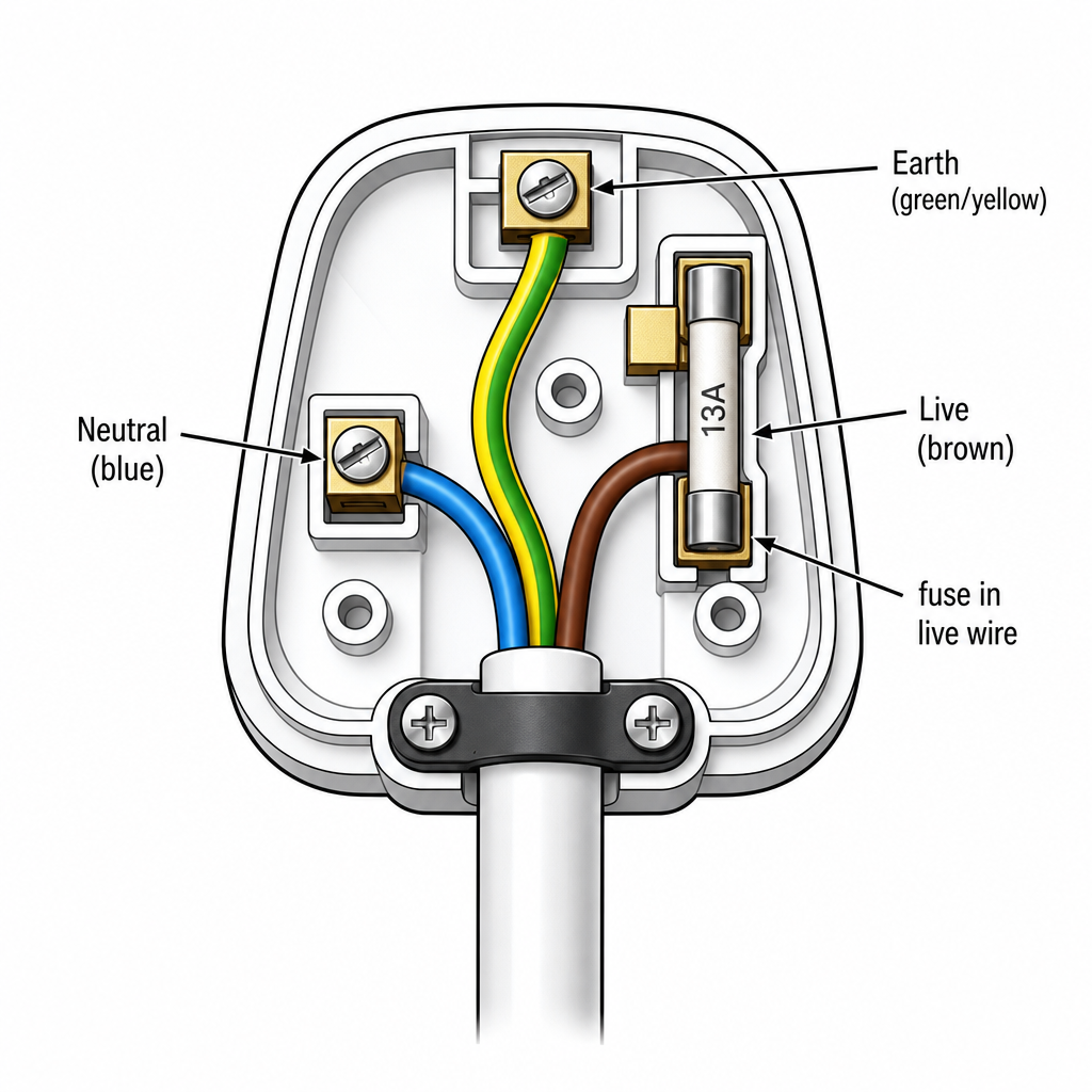
Key idea🔑 Key idea: Live (brown), neutral (blue), earth (green/yellow). Switch and fuse in the live wire, fuse rated just above normal current. The earth wire connects a metal case to earth, so a fault blows the fuse.
Worked example
Worked Example: Choosing a Fuse
Worked Example: Wrong Fuse = Fire 🔥
A V kettle is rated at W. Fuses available are 3 A, 5 A and 13 A. Which should be fitted?
- 1Normal current is A. The fuse must be rated just above this, so the 13 A fuse is correct. A 3 A or 5 A fuse would blow immediately under normal use.
---
12. Electromagnetic Induction
Move a magnet near a coil (or a wire through a field) and you induce an e.m.f. across it; complete the circuit and a current flows. The induced e.m.f. is bigger if you move faster, use a stronger magnet, or add more turns. Lenz's law sets the direction: the induced current always flows so as to oppose the change that caused it, because energy must be conserved. Push a north pole into a coil and the coil's near face becomes north to push back. For a straight wire moving through a field, Fleming's right-hand rule gives the direction of the induced current: thumb = motion, first finger = field (N to S), second finger = induced current.
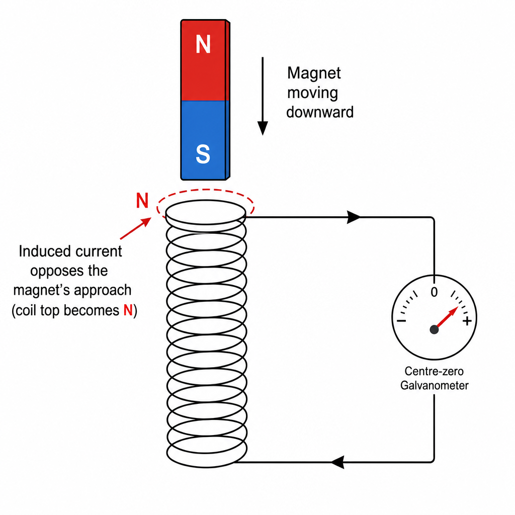
Key idea🔑 Key idea: Faster motion, stronger magnet, more turns → bigger induced e.m.f. Lenz's law: induced current opposes the change causing it (energy conservation). Fleming's right-hand rule for induced current; left-hand rule for the motor effect.
Worked example
Worked Example: Magnet Dropped Through a Coil
Worked Example: Predict the Push 🧲
A magnet is pushed north-pole-first toward a coil. Which pole does the coil's near face become, and why?
- 1By Lenz's law the induced current opposes the approaching north pole, so the coil's near face becomes a north pole to repel it. Opposing the change is what conserves energy: you must do work pushing against that repulsion, and that work becomes the electrical energy.
---
13. The a.c. Generator
Spin a coil in a magnetic field and the changing field through it induces an alternating e.m.f.: that is an a.c. generator. The coil connects to the outside circuit through slip rings and brushes. The output is a sine curve: the e.m.f. is greatest when the plane of the coil is parallel to the field (horizontal in the usual diagram, its sides cutting field lines fastest) and zero when the coil is at right angles to the field (vertical, its sides moving along the lines and cutting none). The rotation itself reverses the e.m.f. every half-turn; the slip rings just keep each end of the coil on its own brush. Spin faster and the output is both bigger and more frequent.
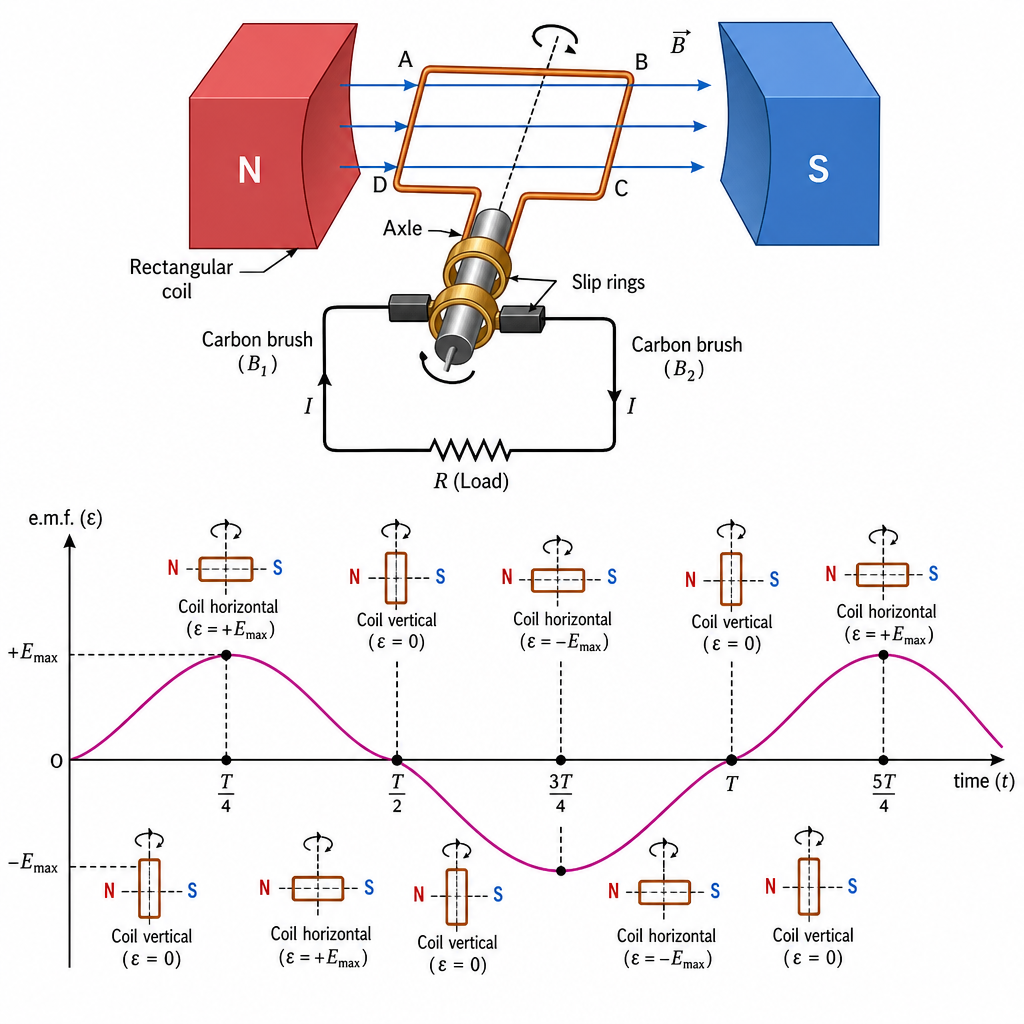
Key idea🔑 Key idea: a.c. generator uses slip rings. Output is a sine wave: max e.m.f. when the coil's plane is parallel to the field (cutting lines fastest), zero when it is at right angles to the field. Faster spin = bigger and higher-frequency output.
Worked example
Worked Example: Reading the Generator Graph
Worked Example: Peaks and Zeros 📉
On a generator's e.m.f.-time graph, the output is momentarily zero. What is the coil doing at that instant?
- 1Zero e.m.f. means the coil's sides are cutting no field lines. That happens when the plane of the coil is at right angles to the field (vertical in the usual diagram): its sides are moving along the lines rather than across them. A quarter-turn later the coil's plane is parallel to the field, its sides cut the lines fastest, and the e.m.f. is at a peak.
---
14. Magnetic Effect of a Current
A current creates a magnetic field around itself. For a straight wire the field is circles around the wire; the right-hand grip rule (thumb along conventional current, fingers curl the field direction) gives its direction. Wind the wire into a solenoid and the fields add to give a field like a bar magnet's, strong and uniform inside. Strengthen it by increasing the current, adding more turns, or inserting a soft-iron core, the basis of the electromagnet.
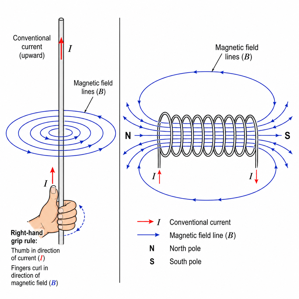
Key idea🔑 Key idea: Straight wire → circular field (right-hand grip rule). Solenoid → bar-magnet field. Stronger with more current, more turns, or a soft-iron core.
Worked example
Worked Example: Field Around a Wire
Worked Example: Right-Hand Grip ✊
Conventional current flows straight up a vertical wire. Use the right-hand grip rule to find the field direction when viewed from above.
- 1Point the right thumb up (current direction); the fingers curl anticlockwise when viewed from above. So the circular field lines run anticlockwise around the wire seen from the top.
---
15. Force on a Current-carrying Conductor
Put a current-carrying wire in a magnetic field and the two fields interact, pushing the wire with a force, the motor effect. Fleming's left-hand rule gives the direction: thumb = force (motion), first finger = field (N to S), second finger = current. The force is bigger with a stronger field or a larger current, and reverses if you reverse either the current or the field. The same sideways push acts on a beam of moving charges, bending it.
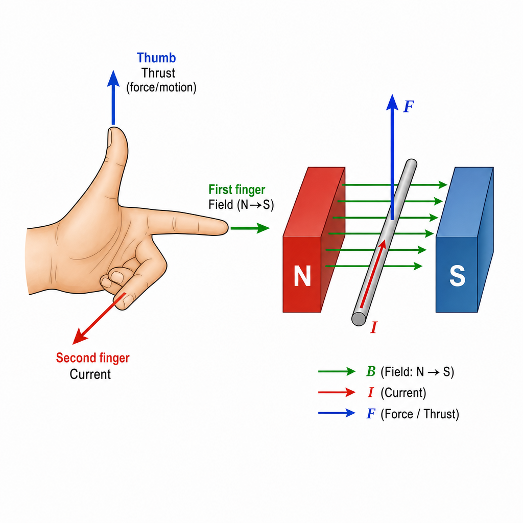
Key idea🔑 Key idea: Motor effect. Fleming's left-hand rule: thuMb = Motion/force, First finger = Field, seCond finger = Current. Reverse current or field → reverse force.
Worked example
Worked Example: Direction of the Force
Worked Example: Left-Hand Check 🤚
A wire carries current from left to right in a field pointing into the page. Which way is the force?
- 1Fleming's left hand: first finger into the page (field), second finger to the right (current), so the thumb points upward. The wire is pushed up the page.
---
16. The d.c. Motor
A d.c. motor is the motor effect made to spin. Current in a coil sitting in a magnetic field feels forces on its two sides, one up and one down, creating a turning effect. The trick is the split-ring commutator: every half-turn it swaps the current direction in the coil, so the forces keep pushing the same rotational way and the coil spins continuously. Increase the turning effect with more current, more turns, a stronger magnet, or a larger coil area.
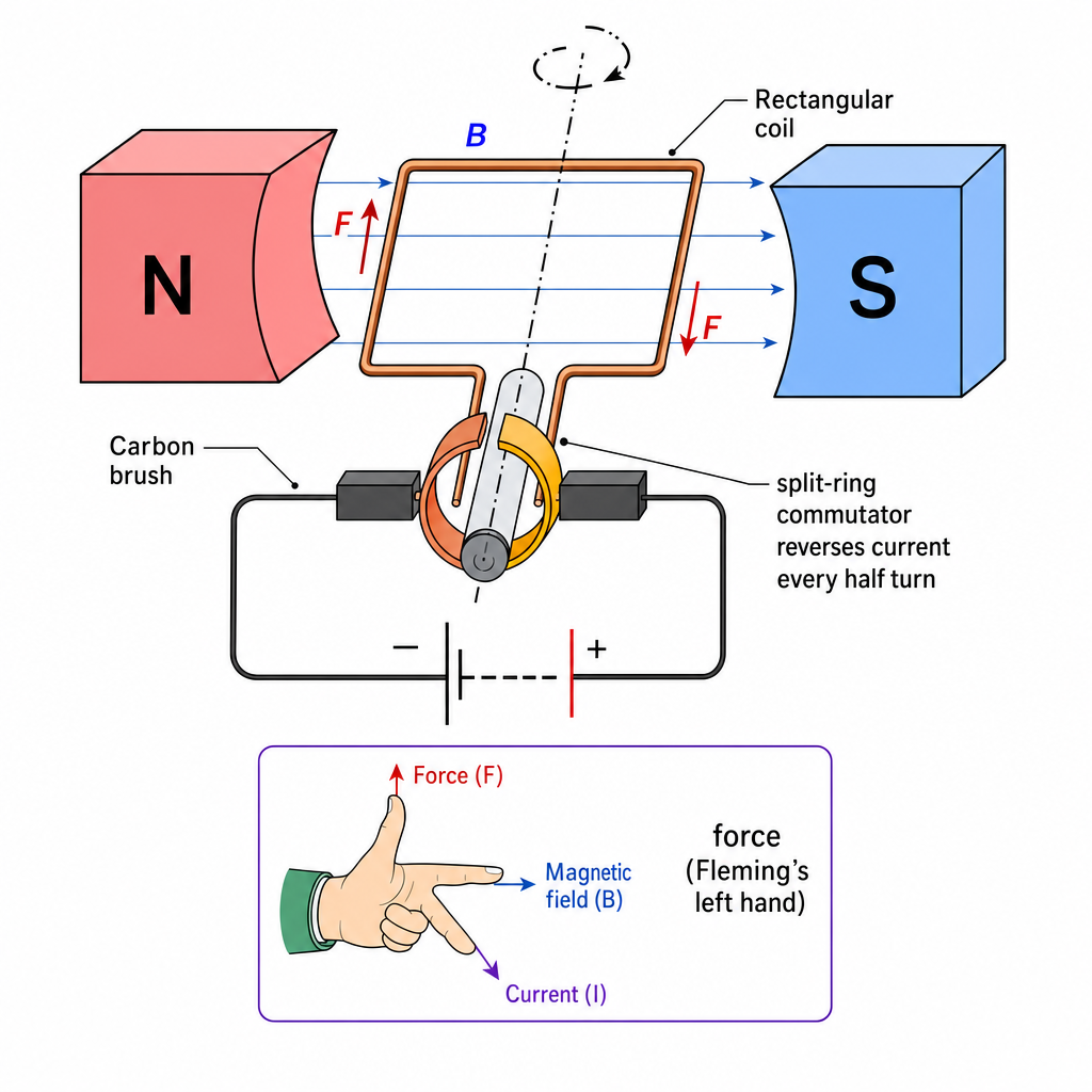
Key idea🔑 Key idea: Opposite forces on the two coil sides make it turn; the split-ring commutator reverses current each half-turn to keep it spinning one way. More current/turns/field/area = stronger turning effect.
Worked example
Worked Example: Why the Split Ring?
Worked Example: Without It, It Stalls 🛑
Explain why a d.c. motor needs a split-ring commutator rather than plain slip rings.
- 1Without it, the coil would turn half a rotation, then the forces would try to push it back, and it would just rock. The split ring reverses the current every half-turn, so the force on each side always drives rotation the same way and the motor spins continuously.
---
17. The Transformer
A transformer changes a.c. voltage. Two coils share a soft-iron core: the alternating current in the primary makes a changing magnetic field that induces an e.m.f. in the secondary. The voltages are in the ratio of the turns, . For an ideal transformer power is conserved, , so stepping voltage up steps current down. That is why power is sent across the country at very high voltage: lower current means far less energy wasted heating the cables ().
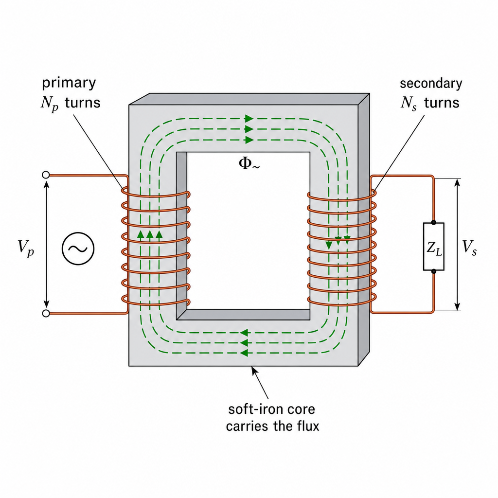
Key idea🔑 Key formulas: ; ideal power . Step voltage up → current down → less loss in transmission.
Worked example
Worked Example: Step-Down Charger
Worked Example: 230 V → 5 V 💻
A phone charger transformer has turns on the primary connected to V a.c. The secondary gives V. How many turns are on the secondary?
- 1Use the turns-voltage ratio , rearranged for :
- 2Far fewer secondary turns (20 vs 920) means a step-down transformer. By , the low-voltage side carries a proportionally larger current.
---
Practice this in the app
Unlock the full chapter: practice questions, flashcards, mock papers and notes, free.
Continue revising